Recent Advances in Electronic Leak Detection
Locating Breaches in Waterproof Membranes has Never Been Easier

Historically, architects and other designers have often called for a flood test to be carried out on horizontal waterproofing systems when the membrane is under a green roof, wear-course or topping slab where direct inspection of the roof membrane is difficult or impossible. ASTM D5957, the Standard Guide for Flood Testing Horizontal Waterproofing Installations, is typically referenced for the test. Flood testing takes from 24 to 48 hours, is often inconclusive and can cause structural damage. As a result, NRCA and CRCA do not recommend conducting flood tests as part of a routine quality-control or quality-assurance program for new roof systems
The first low voltage electronic leak detection (ELD) testing method for waterproof membranes was developed in Europe in the early 80s. Several new ELD methods have been developed since, and they fall in to two main categories: low voltage (48 volts or less) and high voltage (600 volts or more). Although ELD testing has been in use for several decades, no standard describing the methods and limitations had been developed to guide the industry. As a result, there was confusion, misunderstandings and misconceptions surrounding ELD.
In 2014 the ASTM committee on Roofing and Waterproofing released D7877 a standard guide describing the methods using ELD procedures to locate breaches in waterproof membranes. It addresses the need for a systematic procedure to test and verify the integrity of the membrane. The guide describes testing procedures designed to provide an important part of the quality control during membrane installation.
ELD can be used on waterproofing membranes installed in roofs, plaza decks, pools, water features, covered reservoirs, and other waterproofing applications. The procedures are applicable for membranes made of materials such as polyethylene, polypropylene, polyvinyl chloride, bituminous material, as well as semi-conductive membranes such as black EPDM.
All ELD methods described in this guide require a conductive substrate directly under the membrane to serve as a ground return path for the test currents. In roof assemblies where the membrane is installed over an electric insulating material such as insulating foam and/or a protection board, the electric path to any conductive deck is interrupted. In new construction, this situation can be remedied by placing a conductive medium, such as conductive primer, on top of the substrate directly under the membrane. Products like these provide the electrical return path for the test currents, thus enabling valid and conclusive quality control testing of conventional roof membranes.
In 2019, a new ASTM Standard was published. The Standard Practice D8231 provides specific procedures for the Use of a Low Voltage Electronic Scanning System for Detecting and Locating Breaches in Roofing and Waterproofing Membranes. This is the first and only practice to be published regarding ELD testing. D8231 details how the low voltage scanning method has been enhanced to test semi -conductive membranes. This practice also mandates that ELD testing must be performed prior to the placement of overburden to ensure valid results.
The principle of the low voltage ELD method is the establishment of an electrical potential between the waterproof membrane and the underlying conductive substrate. For test methods employing a low voltage electrical potential (48 v or less), a controlled covering of water on the surface forms the conductive path horizontally across the membrane to any membrane breach (Figure 1). At a breach location, an electrical path is formed through the water, through the membrane to the conductive substrate below. A sensitive receiver detects the leakage current and alerts the operator.

Figure 1 – Basic circuit for low voltage leak location method
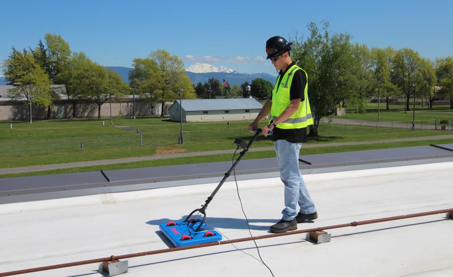
Low Voltage Horizontal Membrane Scanning Platform
The principle of the scanning platform method is to establish a voltage potential between the platform and the conductive substrate, tracking any leakage current passing through the membrane. This is accomplished by wetting the surface of the membrane, applying a voltage with respect to the grounded substrate and then locating areas where electrical current flows from the platform through membrane breaches to the conductive substrate.

Figure 2 – Basic circuit scanning platform
The basic circuit and application of a dual sweep scanning platform is shown in Figure 2. The platform is constructed with two sets of metal sweeps which make continuous electrical contact with the membrane surface. The outer sweep forms a continuous perimeter around the platform with the inner sweep contained within the outer sweep. The positive terminal of the equipment’s electronics is attached to a grounded object (concrete or metal) and the negative terminal connects to the platform. Since most roofing and waterproofing membranes are non-conductive, the electrical potential applied to the platform sweeps provides a path through the water to any breach, thus completing the electrical circuit to the conductive substrate and back to the electronics.
During the membrane scan (Figure 3), water is applied to the surface of the membrane. The testing area must be sufficiently wet as water must travel through any voids in the membrane to the conductive substrate.

Figure 3: Membrane scanning
The inner sweep, which is electrically shielded by the outer sweep, will detect a leakage current when the unit is directly over the membrane defect. This will result in a noticeable deflection on the inner sweep meter accompanied by an audible alert. This is precisely the location where moisture is penetrating the membrane.
Low-Voltage Vertical Membrane Surface Scanning
The vertical scanning system provides leak testing on vertical surfaces, corners, foundation, parapet walls, and seams ensuring that difficult to inspect details are watertight.
As illustrated in Figure 4, the vertical leak locate system employs a sensitive receiver with an audible and visual alarm, a water moistened sensor, and a ground lead. The receiver supplies the power source referenced to ground for testing the membrane integrity.

Figure 4: Basic circuit of vertical surface scanner
In operation, the moistened sensor, which is connected through a cable to the voltage source in the receiver, is pressed against the surface under test (Figure 5). This action forces water onto the membrane surface and into any breaches. A leakage current will flow from the ground connection through breach location, returning to the receiver through the moistened sensor. The receiver will register a deflection on the signal level meter accompanied by an audible alert.

Figure 5: Vertical scanning
Building Enclosure Monitoring
A proactive preventative maintenance program for roof systems begins with quality control inspection and testing. It can then be followed up with an embedded electronic monitoring system to provide a continuous evaluation of the roof performance over the service life of the membrane. This is particularly important for roof systems over critical buildings such as hospitals, data centers, museums, etc. or where a protected assembly has heavy over burden or a vegetative covering.
Construction monitoring can assure that the roof was installed correctly and alert project managers if issues occur while other work is being performed on the roof. Monitoring can be continued for the life of the roof assuring breaches are located early and water damage is kept to a minimum.
Conclusion
Although ELD methods for locating breaches in waterproofing membranes have been in use for several decades, new technology and ASTM Standard Practice D8231 provides clear direction to the industry on requirements for valid ELD testing. Adhering to an ASTM Standard Practice provides specific documentation for all sectors of the building community to use as a benchmark for appropriately specifying and utilizing ELD. ELD is cost-effective preventative maintenance and provides risk mitigation to create peace of mind for all stakeholders
Looking for a reprint of this article?
From high-res PDFs to custom plaques, order your copy today!


